
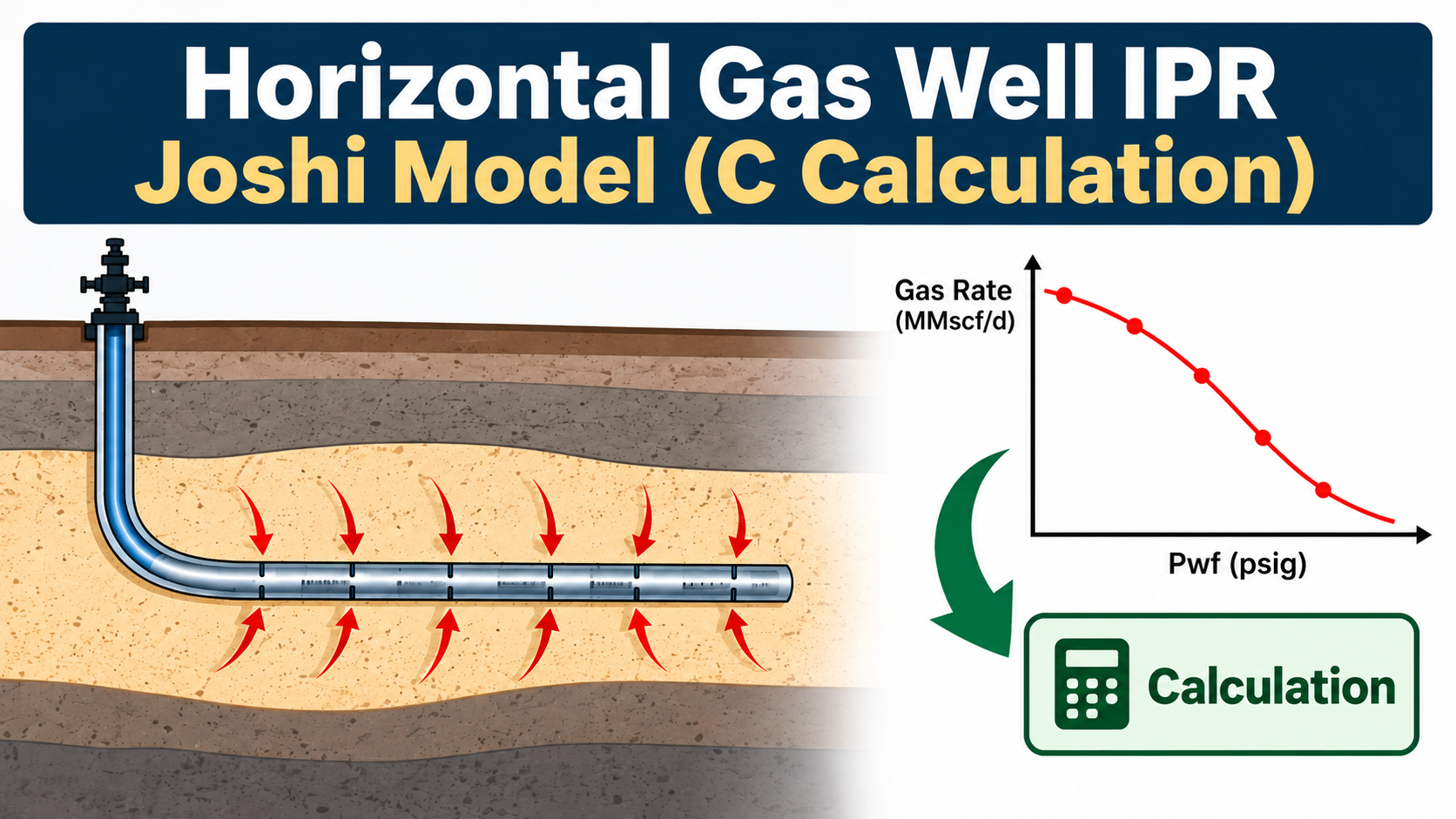
Horizontal gas wells can have significantly different inflow performance from conventional vertical wells. When a development horizontal well needs to be calibrated from an existing vertical DST, simply transferring the DST deliverability coefficient C is generally not sufficient.
A practical engineering workflow is to use the Joshi horizontal-well productivity model to generate a physically based horizontal-well inflow performance relationship (IPR), while retaining the tested gas deliverability exponent n from the DST.
The resulting Joshi IPR can then be converted into an equivalent C–n deliverability representation for use in nodal-analysis and production-system software.
- Why Is Horizontal-Well IPR Different?
A vertical well and a horizontal well expose the reservoir to flow in fundamentally different ways.
A vertical DST may test only a limited perforated interval, while a horizontal open-hole well may contact a much larger section of the reservoir.
Important parameters include:
- Horizontal permeability, kh
- Vertical permeability, kv
- Reservoir thickness, h
- Horizontal well length, L
- Drainage radius, re
- Wellbore radius, rw
- Horizontal-well skin, S
- Gas viscosity, μg
- Gas compressibility factor, Z
- Reservoir pressure, Pr
- Flowing bottomhole pressure, Pwf
Therefore, the development-well IPR should ideally be calculated using the actual horizontal-well geometry rather than simply copying the vertical DST C value.
The key concept is:
Use the DST to establish the tested gas deliverability behaviour, but use the development-well geometry and reservoir assumptions to calculate the horizontal-well IPR.
2. Recommended Engineering Workflow
A practical workflow is:
Vertical DST → PVT → Gas pseudopressure → DST kh → Partial-penetration assessment → Development kh → Joshi horizontal IPR → Equivalent C–n representation
This separates the interpretation of the original DST from the modelling of the development horizontal well.
This is particularly useful when the development-well permeability, horizontal length, or skin is different from the conditions represented by the DST.
3. Permeability Anisotropy
The Joshi model accounts for different horizontal and vertical permeability.
The anisotropy factor used in the formulation is:
where:
- kh = horizontal permeability
- kv = vertical permeability
- β = permeability anisotropy factor
For example, if:
then:
and:
A stronger permeability contrast changes the effective flow resistance around the horizontal well.
4. Why Gas Pseudopressure Should Be Used
For gas wells, viscosity and compressibility factor vary with pressure.
Using constant gas properties can therefore introduce significant simplification, particularly over a large pressure drawdown.
Gas pseudopressure accounts for the pressure dependence of gas properties:
where:
- p = absolute pressure
- μg = gas viscosity
- Z = gas compressibility factor
- m(p) = gas pseudopressure
Pressure must be expressed as absolute pressure in the pseudopressure calculation.
Therefore:
approximately at standard atmospheric pressure.
5. Numerical Calculation of Pseudopressure
In a spreadsheet or calculator, the integral can be evaluated numerically using the trapezoidal method.
For two consecutive PVT pressure points:
The accumulated pseudopressure is then:
The pseudopressure difference between reservoir pressure and flowing pressure is:
One practical advantage of this approach is that the calculation can be directly audited against the supplied PVT table.
6. Interpolating Pseudopressure
The required reservoir or flowing pressure will not always correspond exactly to a PVT table pressure.
For example, a PVT table may contain:
- 2000 psig
- 2300 psig
- 2800 psig
while the required pressure may fall between these values.
In that situation, the accumulated pseudopressure is interpolated between the surrounding PVT points.
This provides:
and:
Then:
The same interpolation procedure can be applied at every flowing pressure used to generate the horizontal-well IPR.
7. Estimating Apparent DST Permeability
The vertical DST can first be interpreted using an appropriate radial-flow model.
A simplified gas pseudopressure relationship can be represented as:
where:
- q = gas rate
- kh = effective horizontal permeability
- h = tested reservoir thickness
- Δm = gas pseudopressure difference
- TR = reservoir temperature in Rankine
- D = flow-resistance term
For a simple radial-flow reference case:
where:
- re = drainage radius
- rw = wellbore radius
The resulting permeability should be regarded as an apparent or effective DST permeability, subject to the assumptions of the selected interpretation model.
It should not automatically be treated as the development horizontal-well permeability.
8. Partial Penetration of the DST
Partial penetration can be important when the DST tests only part of the reservoir.
For example:
Total reservoir thickness = 75 m
while:
DST tested interval = 10 m
The DST therefore does not necessarily represent full-thickness reservoir inflow.
An appropriate partial-penetration correlation can be used to assess the effect.
One Odeh-type formulation can be expressed as:
where:
- ht = total reservoir thickness
- hp = tested/perforated interval
- kH = horizontal permeability
- kV = vertical permeability
- rwc = corrected wellbore radius
The exact formulation, units, and assumptions should be checked against the original correlation source before application.
9. Do Not Double-Count Partial Penetration
This is an important engineering distinction.
There are two separate concepts:
DST interpretation
Partial-penetration effects can be considered when interpreting what the DST permeability represents.
Development horizontal well
The horizontal well has its own geometry and potentially its own completion-related skin.
Therefore:
A partial-penetration correction should not simply be added again as horizontal-well skin if its effect has already been accounted for elsewhere.
10. Keep Development-Well kh Editable
For a development horizontal well, it is useful to keep kh as an independent engineering input.
For example:
| Case | kh |
|---|---|
| Low | User input |
| Base | User input |
| High | User input |
This is particularly useful for heterogeneous reservoirs where permeability can vary significantly spatially.
A DST-derived permeability can therefore be retained as:
- A reference case
- A calibration case
- A sensitivity case
rather than automatically forcing the development well to use exactly the same permeability.
11. Joshi Horizontal-Well Model
The Joshi model accounts for the geometry of the horizontal well and the surrounding reservoir.
A commonly used geometric parameter is:
where:
- L = horizontal well length
- reh = effective drainage radius
If a drainage area A is used:
The Joshi flow-resistance term can then be expressed as:
This term represents the geometric flow resistance associated with the horizontal-well configuration.
12. Horizontal Gas-Well Inflow Using Pseudopressure
The horizontal-well gas inflow can then be represented as:
where:
- qg = gas production rate
- kh = horizontal permeability
- h = reservoir thickness
- Δm = gas pseudopressure difference
- TR = reservoir temperature in Rankine
- DJoshi = Joshi flow-resistance term
- S = horizontal-well skin
The constant and unit system must remain consistent with the implementation.
The important point is that Δm changes with Pwf, and therefore the calculated Joshi rate changes with flowing pressure.
13. Horizontal-Well Skin Should Be an Independent Input
Skin is not necessarily a fixed reservoir property.
For a horizontal open-hole well, the effective skin may be influenced by:
- Formation damage
- Cleanup
- Near-wellbore permeability
- Completion condition
- Open-hole exposure
- Completion quality
- Reservoir heterogeneity
It is therefore useful to test a range of skin values.
For example:
- S = −4
- S = −2
- S = 0
- S = +1
- S = +2
This provides a sensitivity range instead of assuming that one skin value applies universally.
14. Generate the Complete Horizontal IPR
A key advantage of the approach is that the horizontal-well flowing pressure does not need to be fixed at one operating point.
Instead, calculate the Joshi rate at multiple Pwf values.
For example:
| Pwf | Joshi q |
|---|---|
| High Pwf | Low rate |
| ↓ | ↓ |
| Medium Pwf | Medium rate |
| ↓ | ↓ |
| Low Pwf | High rate |
This generates a complete horizontal-well IPR curve.
The complete IPR is more informative than calculating only one production rate at one assumed flowing pressure.
15. Converting the Joshi IPR to C–n
Many production and nodal-analysis software packages represent gas deliverability using a C–n relationship.
A common form is:
The exact pressure convention and units must always be checked against the target software.
For the Petrotopic methodology, the DST deliverability exponent is retained:
For each Joshi IPR point, an equivalent C can then be calculated as:
When C is reported in Mscf/d:
The use of absolute pressure is important because the pressure term is based on psia, not psig.
16. Reference C, Equivalent C Range, and Best-Fit C
Because the Joshi model uses PVT-dependent pseudopressure while the C–n relationship uses a simplified pressure function, the equivalent C calculated at each Pwf does not necessarily remain constant.
Therefore, the Petrotopic calculator distinguishes three concepts.
16.1 Recommended C — Reference Pwf
The recommended C is calculated at the selected Reference Pwf:
where:
This ensures that the C–n relationship reproduces the Joshi rate exactly at the selected reference flowing pressure.
16.2 Equivalent C Range over IPR Pwf Range
For every calculated IPR point:
The calculator then reports:
This is the Equivalent C Range over the selected IPR Pwf range.
It shows how much the equivalent C changes as Pwf changes.
It is a diagnostic range, not automatically the final C to be entered into software.
16.3 Best-Fit C — Diagnostic
A single C can also be obtained by least-squares fitting while keeping n fixed:
This provides a useful diagnostic of how well one constant C represents the complete Joshi IPR.
However, the best-fit C should be clearly identified as a diagnostic value when the engineering workflow specifically uses the Reference-Pwf C as the recommended coefficient.
17. NRMSE — How Good Is the C–n Representation?
The quality of the fixed-n C–n representation can be assessed using Normalized Root Mean Square Error (NRMSE).
NRMSE compares the C–n representation with the original Joshi IPR over the selected Pwf range.
A lower NRMSE indicates closer agreement.
For example:
NRMSE = 1.68%
indicates very close agreement between the calculated C–n representation and the Joshi IPR over the selected range, subject to the normalization method used.
NRMSE should be interpreted as a curve-fit diagnostic, not as an uncertainty estimate for the reservoir.
18. Example Engineering Data
Consider a development horizontal-well case:
| Parameter | Example |
|---|---|
| Reservoir thickness | 75 m |
| Horizontal well length | 548 m |
| Drainage radius | 500 m |
| Wellbore radius | 0.122 m |
| kv/kh | 0.1 |
| Horizontal permeability | 50 mD |
| Horizontal skin | 0 |
| Reservoir pressure | 2300 psig |
| DST n | 0.89202 |
The anisotropy factor is:
These values are illustrative. Actual reservoir and well-specific inputs should be used for engineering application.
19. DST Permeability Versus Development Permeability
It is useful to keep the following concepts separate.
DST apparent permeability
Derived from interpretation of the tested DST.
It reflects the tested interval and the assumed DST flow geometry.
DST corrected permeability
A partial-penetration correction may be applied to assess what permeability could represent a larger reservoir thickness.
Development kh
The permeability selected for the horizontal development-well model.
It may be:
- Taken from a geological model
- Calibrated from DST interpretation
- Calibrated against nearby wells
- Selected as a sensitivity parameter
There is no requirement that these three values be identical.
20. What the Petrotopic Calculator Provides
The Petrotopic calculator brings the workflow into a single engineering tool.
Input
The user can enter:
- kh
- kv/kh
- Reservoir thickness
- Horizontal well length
- Drainage radius
- Wellbore radius
- Horizontal-well skin
- Reservoir pressure
- Reference Pwf
- Gas deliverability exponent n
- Reservoir temperature
- Gas PVT data
- IPR Pwf range
Calculation
The calculator then:
- Processes the PVT table.
- Converts pressure to absolute pressure where required.
- Calculates gas pseudopressure.
- Interpolates m(Pr) and m(Pwf).
- Calculates Δm.
- Calculates the Joshi geometry.
- Calculates the horizontal-well inflow rate.
- Generates the complete IPR.
- Calculates equivalent C at each IPR Pwf.
- Reports the Equivalent C Range over the selected IPR Pwf range.
- Calculates the Recommended C at the Reference Pwf.
- Calculates a Best-Fit C as a diagnostic.
- Calculates NRMSE to assess the agreement between the C–n representation and the Joshi IPR.
21. Why This Approach Is Useful for Production-System Software
A reservoir engineer may have a detailed horizontal-well inflow model but ultimately need a practical inflow relationship for a nodal-analysis or production-system model.
The Joshi model provides the physical basis.
The resulting simplified deliverability relationship can then be represented as:
This creates a transparent link between:
DST → PVT → reservoir properties → horizontal-well geometry → Joshi IPR → C–n deliverability
while retaining the tested DST n.
22. Important Limitations
The Joshi model is an analytical productivity model. It should not be interpreted as a complete reservoir simulation.
The basic analytical approach does not automatically reproduce:
- Complex natural fractures
- Explicit dual-porosity behaviour
- Explicit dual-permeability behaviour
- Strong reservoir heterogeneity
- Complex pressure-dependent permeability
- Detailed transient multiphase effects
- Detailed completion inflow distribution
- Water or condensate effects
Therefore, the calculated C should be considered a representative engineering deliverability coefficient, not a universal reservoir constant.
The applicability of the Joshi model and any partial-penetration correlation should also be checked against the actual reservoir, completion, and flow assumptions.
23. Recommended Sensitivity Analysis
For development planning, it is useful to test at least the following sensitivities.
Permeability
Low kh → Base kh → High kh
Skin
Negative skin → Zero skin → Positive skin
Reservoir pressure
Low Pr → Base Pr → High Pr
Horizontal length
Shorter L → Base L → Longer L
Pwf range
Test the Pwf range relevant to the expected operating conditions.
This helps identify which assumptions have the greatest effect on:
- Horizontal-well IPR
- Equivalent C
- Recommended C
- Deliverability
24. Practical Workflow Summary
The complete methodology can be summarized as follows.
Step 1 — DST
Obtain:
↓
Step 2 — PVT
Prepare:
↓
Step 3 — Pseudopressure
Calculate:
↓
Step 4 — DST Permeability
Calculate the apparent/effective DST permeability using the selected DST interpretation model.
↓
Step 5 — Partial Penetration
Assess the impact of the tested interval.
↓
Step 6 — Development kh
Select an appropriate permeability for the development horizontal well.
↓
Step 7 — Horizontal Geometry
Enter:
↓
Step 8 — Horizontal Skin
Apply the selected development-well skin.
↓
Step 9 — Joshi IPR
Calculate the horizontal-well rate at multiple Pwf values.
↓
Step 10 — Equivalent C
For each Pwf:
↓
Step 11 — Recommended C
Use the selected Reference Pwf to calculate the recommended C.
↓
Step 12 — Diagnostic Check
Calculate:
- Equivalent C Range
- Best-Fit C
- NRMSE
to understand how well a constant-C, fixed-n relationship represents the Joshi IPR.
25. Final Takeaway
The objective is not simply to calculate a new C from one arbitrary horizontal-well pressure point.
A more transparent engineering approach is to:
Use the DST to establish the tested gas deliverability exponent, use PVT pseudopressure to account for pressure-dependent gas properties, use the Joshi model to represent horizontal-well geometry, generate the complete horizontal-well IPR, and then convert that IPR into an equivalent C–n representation.
The Petrotopic methodology keeps:
n = nDST
while the horizontal-well model determines the corresponding deliverability.
The resulting outputs can then be viewed separately:
- Recommended C — based on the selected Reference Pwf
- Equivalent C Range over IPR Pwf Range — shows C variation across the calculated IPR
- Best-Fit C — diagnostic least-squares value
- NRMSE — diagnostic measure of agreement between the C–n representation and the Joshi IPR
This provides a transparent connection between the tested vertical DST, the horizontal development well, and the simplified inflow relationship required by production-system software.
Try the Calculator
Horizontal Gas Well — Joshi C Calculator
The Petrotopic calculator allows engineers to change:
- kh
- kv/kh
- Horizontal well length
- Reservoir thickness
- Drainage radius
- Wellbore radius
- Horizontal-well skin
- Reservoir pressure
- Reference Pwf
- DST n
- PVT data
- IPR Pwf range
and immediately evaluate the resulting horizontal-well IPR, equivalent C range, recommended C, best-fit C, and NRMSE.
Engineering Note
The equations presented above are simplified for practical engineering implementation. Always verify the unit system, pressure convention, correlation applicability, reservoir assumptions, and target software input convention before using a calculated C in an actual well model.